
However, if the transport block is divided into subsets – let’s assume 3 subsets – then the UE will send NACK for only the failed subset and the gNB will only need to retransmit the failed subset instead of the whole transport block. The advantage of this approach is that since 5G will be supporting huge Transport Block Sizes (TBS) and the scheduler usually works with a 10% BLER target so this means that if the gNB is transmitting data to a UE with huge TBS, around 10% of this data will be retransmitted. These groups will be decoded by the UE and the UE will send HARQ feedback for each of the individual groups.
#5g spectral efficiency code#
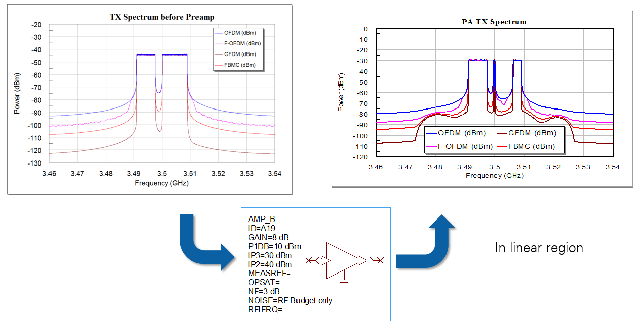
5G NR introduces a concept of Code Block Groups (CBGs) which will essentially divide the transport blocks in smaller groups. I explained this in my previous article but since it is related to spectral efficiency as well so I will summarize it again. Later on, once it gets its own allocations, it will get its own UE specific RS so there should be no issue. However, in 5G, the SSB which is the PSS/SSS/PBCH block will always be transmitted at regular intervals and this block will have its own RS which might be used for the UE for the sake of this initial selection or reselection. If these signals are not present then the UE will not be able to get an accurate RSRP for the cell during selection or reselection process. This approach raises a question for cell selection and reselection process as UEs use the CRS during these processes in 4G to estimate a RSRP and to choose the best cell. An increase in CQI means an increase MCS and spectral efficiency. This will reduce the overall interference in the system and will increase the average CQI. In 5G, the user specific DMRS will be used which means that each user will have its own RS within its allocation and if there is no allocation then there will be no RS. 5G eliminates the usage of CRS as it tries to minimize signals that are always active. However, the CRS are being transmitted continuously in 4G which results in significant downlink interference. The concept of CRS is pretty important in 4G as UEs use the CRS to estimate the channel. This provides another gain in the spectral efficiency of 5G. For 4G, only 250 RBs are used with a 50 MHz spectrum. In 5G, enhanced techniques like F-OFDM are used which lets 5G use much more bandwidth and as can be seen a total of 275 RBs can be used in 50 MHz. This shows that in a channel of 10 Mhz, only 9 MHz is utilized while around 1 MHz is left as a guard band. As each subcarrier has a spacing of 15 kHz, so these 600 subcarriers will take a total of 9000 kHz or 9 MHz. So, this gives us a total of 600 subcarriers per 10 MHz 4G channel. This can be seen by the fact that a 10 MHz 4G channel has 50 RBs and each RB has 12 subcarriers. The current 4G technology uses a guard band of approximately 10%. The concept of inherent guard band has been revolutionized in 5G. This means that from 2nd slot onwards, the overhead of PDCCH will be zero and all the symbols will be used to transmit data increasing the capacity and spectral efficiency of the system. Then, it will read all the 5 slots and there will be no PDCCH from 2nd slot onwards. So, the UE will read the PDCCH and it will find out that the PDCCH has assigned 5 slots or TTIs to the UE including the first one. So, if the UE has a significant amount of data then the gNB can assign a PDCCH that allocates multiple slots to that UE. The main idea is that the gNB has the downlink data in its buffer so it knows the amount of bits that are present or atleast it can estimate the incoming bit rate for a specific UE. However, 5G introduces a concept of slot aggregation where it is not mandatory to have PDCCH in all TTIs. The advanced PDCCH algorithms reduce this overhead by reducing the control symbol utilization but still PDCCH has to exist in every subframe and therefore, its overhead is always there. Usually, a 4G subframe consists of 14 symbols and PDCCH can utilize 3 of these 14 symbols which is around 20% overhead. The UE reads the PDCCH which tells the UE where its data is located on the PDSCH. The PDCCH carries the control and scheduling information while the PDSCH carries the data or traffic. In 4G, each TTI has two main parts – PDCCH and PDSCH.


 0 kommentar(er)
